Hardware Build and Deployment
A model where all layers have been converted to either HLS or RTL layers can be processed by FINN to build a bitfile and driver targeting a Zynq or Alveo system or to generate a Vivado IP Integrator (IPI) design with AXI stream (FIFO) in-out interfaces, which can be integrated onto any Xilinx FPGA as part of a larger system.
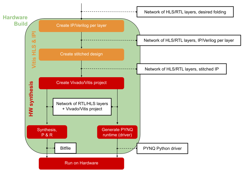
Hardware Build
Internally, the hardware build consists of the following steps:
Driver generation
DMA and DWC node insertion
Partitioning for floorplanning
FIFO insertion and IP generation
Vivado/Vitis project generation and synthesis
Note
In previous FINN releases it was necessary to step through the individual sub-steps for hardware build manually by calling each transformation. The hardware build transformations ZynqBuild now execute all necessary sub-transformations. For more control over the build process, the transformations listed below can still be called individually.
Driver Generation
To rapidly test the generated design on PYNQ platforms, FINN is capable of
generating a Python driver for the given design. This driver packs/unpacks the
input/output tensors in the expected format, then uses PYNQ APIs to initiate
data movement and transfer back the results to the host CPU. The generation of
the driver is done by transformation pass finn.transformation.fpgadataflow.make_pynq_driver.MakePYNQDriver.
DMA and DWC Node Insertion
At this step, FINN will insert custom hardware-oriented ONNX nodes into the graph.
These are DMA engines for moving data into and out of the accelerator (from DRAM),
and data width converters between consecutive nodes where required.
These steps are accomplished by calling the finn.transformation.fpgadataflow.insert_iodma.InsertIODMA
and finn.transformation.fpgadataflow.insert_dwc.InsertDWC transformations,
respectively.
Partitioning for Floorplanning
FINN will now partition the graph into several StreamingDataflowPartitions.
This capability is most to facilitate floorplanning for future FINN releases
and does not alter the functioning of the model itself. Each DMA node will be
placed into its own partition. If no partition number attributes are specified,
all the regular network nodes will become a single partition.
This is accomplished by the finn.transformation.fpgadataflow.floorplan.Floorplan
and finn.transformation.fpgadataflow.create_dataflow_partition.CreateDataflowPartition
transformations.
Note
For Vitis, each partition will be compiled as a separate kernel, and linked together afterwards. For Zynq, each partition will become an IP block.
FIFO Insertion and IP Generation
FINN will descend into each partition and insert FIFO nodes between streaming nodes,
where FIFO depths dictated by the node attributes, using the finn.transformation.fpgadataflow.insert_fifo.InsertFIFO
transformation.
Afterwards, IP blocks will be created for each partition, which in turn contain the
IP blocks for HLS layers and RTL modules for RTL layers stitched together. The layer-level IP blocks for HLS layers
are generated by Vitis HLS, using a sequence of finn.transformation.fpgadataflow.prepare_ip.PrepareIP
and finn.transformation.fpgadataflow.hlssynth_ip.HLSSynthIP transformations.
For RTL layers calling finn.transformation.fpgadataflow.prepare_ip.PrepareIP will fill out the RTL wrapper files and store all files belonging to the RTL module in a folder.
The top-level IP blocks are generated in Vivado IPI, using the finn.transformation.fpgadataflow.create_stitched_ip.CreateStitchedIP transformation.
Vivado/Vitis Project Generation and Synthesis
The final step in the hardware build flow is to generate a Vivado (for Zynq) or Vitis (for Alveo) project, and run synthesis to generate a bitfile. This is done using the MakeZYNQProject transformation for Zynq, and the VitisLink transformation for Alveo.
Deployment
The bitfile and the driver file(s) can be copied to the PYNQ board and be executed there. For more information see the description in the end2end_example Jupyter notebooks.